
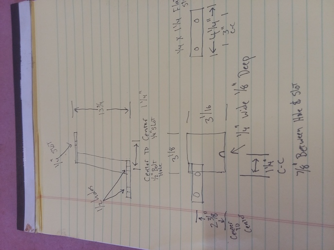
Zane's family got so many requests for the jig they decided they would put the plans in the public domain so anyone interested could build one. Below are the instructions as best as I know them to be copied from Zane's instructions. Any corrections are welcomed.
Move the mode lever to the up position control.
The lift arms should be all the way down and the touch control handle all the way to the bottom of it travel in the quadrant.
Hold the flat threaded plate of the position control linkage adjustment with a large adjustable crescent wrench and loosen the jam not with a 9/16" end wrench several turns off the flat plate.
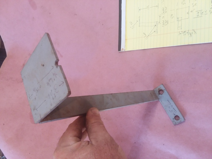
Using a 5/8" open wrench, turn the adjusting bold with the narrow flats on its end that comes in contact with the control rod until the control rod is aligned with the notch in the adjusting jig while holding the slack to the back on the control rod. Re-tighten the jam nut while assuring the adjustment bolt does not turn and change the adjustment.
When the lift is reattached to the tractor differential pump housing, the lift control rod must be guided down behind the pump housing and into the control valve socket by holding the lift up slightly with the left hand on the yoke of the draft spring and with the right hand reaching over the right rear axle housing and feeling the control valve socket with the right hand as the control rod is put in the socket. If the control rod is not properly seated into the control valve socket, the lift will not work. This is best done with a helper or a chain hoist to assist the lowering of the lift housing into place.
Install the two bolts that are on either side of the oil pressure supply hole in the lift cover assembly and put the pins in the lift arms to the lift links. With the selector lever in the draft mode (down), start the engine and see if the lift will pick up the arms when the touch control handle is moved to within about one inch of the top of its uppermost travel in the quadrant. If it starts to come up before the lever is one 1" or less from the top of it travel, loosen the 4 quadrant bolts and bump it either forward or backward to adjust the position on the quadrant when the lift starts up. It should start up approximately 1" from the top of the travel of the touch control handle.
Now place the mode selector lever (small lever) in the position control (up) position and move the touch control handle all the way down in the quadrant. The lift arms should go all the way to the bottom of their travel. Move the touch control handle up in increments and the lift arms should move up in increments corresponding to the movement of the touch control handle until the lift arms are all the way to the top and the touch control handle is also all the way to the top.
This process should now have the lift in near perfect adjustment so that both the draft and the position controlled implements and attachments on the lift.